Home

tuyau responsabilité Construire diode 0.7 v poulet terrain de jeux Dominant

In the circuit shown in figure, the silicon and germanium diodes

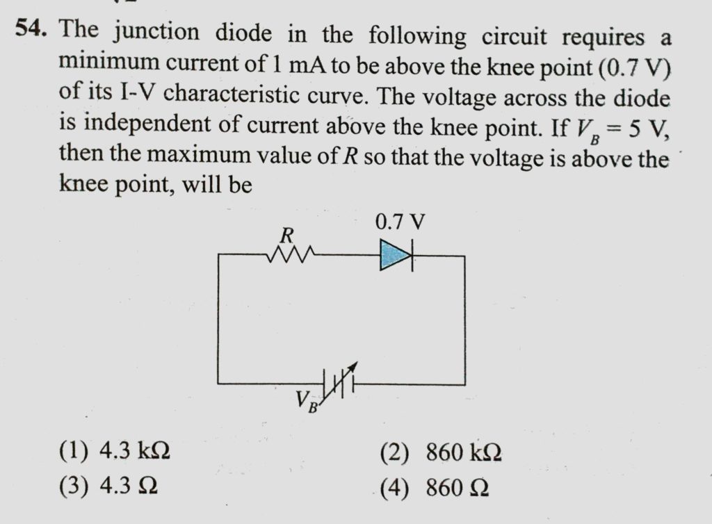
The junction diode in the following circuit requires a minimum current of 1  mA to be above the knee point (0.7 V) of its I-V characteristic curve. The  voltage across the diode
The junction diode in the following circuit requires a minimum current of 1 mA to be above the knee point (0.7 V) of its I-V characteristic curve. The voltage across the diode

Signal Diode and Switching Diode Characteristics

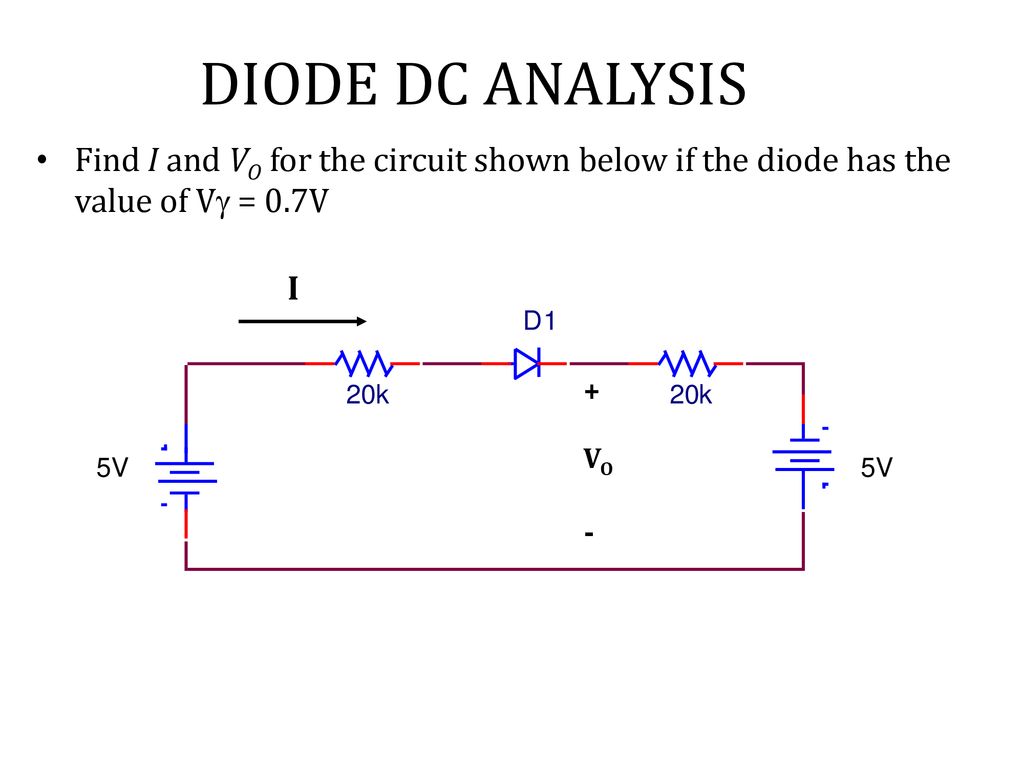
Recall-Lecture 5 DC Analysis Representation of diode into three models -  ppt download
Recall-Lecture 5 DC Analysis Representation of diode into three models - ppt download

Electronics tutorial - section 13

100pc Schottky Diode SB260 2A 60V Vd=0.7V @2A RoHS Electronic Components &  Semiconductors Semiconductors & Actives
100pc Schottky Diode SB260 2A 60V Vd=0.7V @2A RoHS Electronic Components & Semiconductors Semiconductors & Actives

https://docs.google.com/document/d/1YC8r_yWQZVjNx1lFxJe0wYCKpn1EEd7hCNx6SK5zjMw/edit

Ge and Si diodes start conducting at 0.3 V and 0.7 V respectively. In the  following
Ge and Si diodes start conducting at 0.3 V and 0.7 V respectively. In the following

Ge and Si diodes start conducting at 0.3V and 0.7V respectively. - Sarthaks  eConnect | Largest Online Education Community
Ge and Si diodes start conducting at 0.3V and 0.7V respectively. - Sarthaks eConnect | Largest Online Education Community

Get Answer) - 1. Analyze the circuit below using an ideal diode + voltage  source...| Transtutors
Get Answer) - 1. Analyze the circuit below using an ideal diode + voltage source...| Transtutors

How do we measure cut-in voltage of diode? - Quora

Ge and Si diodes start conducting at 0.3 V and 0.7 V respe

Signal Diode and Switching Diode Characteristics

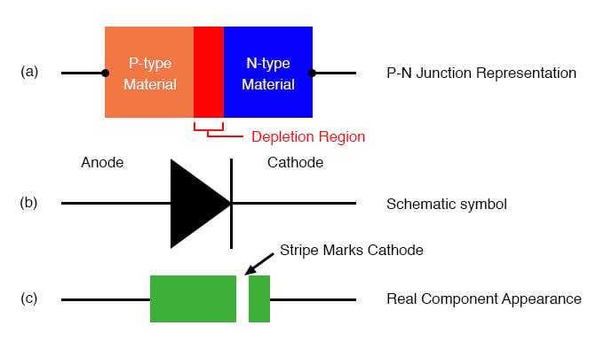
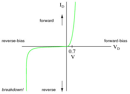
Introduction to Diodes And Rectifiers | Diodes and Rectifiers | Electronics  Textbook
Introduction to Diodes And Rectifiers | Diodes and Rectifiers | Electronics Textbook

How can a diode work as a rectifier with a voltage drop of 220v if the diode  can only withstand 5v? - Quora
How can a diode work as a rectifier with a voltage drop of 220v if the diode can only withstand 5v? - Quora

Ge and Si diodes conduct at 0.3 V and 0.7 V respectively. In the f

What Are Zener Diodes? | Diodes and Rectifiers | Electronics Textbook

Answered: Q8 Assume V,-0.7 V for each diode for… | bartleby

A diode made of silicon has a barrier potential of `0.7 V` and a current of  `20 mA` passes through t - YouTube
A diode made of silicon has a barrier potential of `0.7 V` and a current of `20 mA` passes through t - YouTube

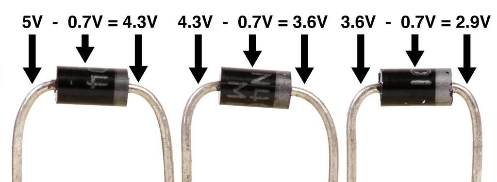
Diodes : 7 Steps - Instructables

52 Active Device Technologies - conocimientos.com.ve: DIODES AND RECTIFIERS

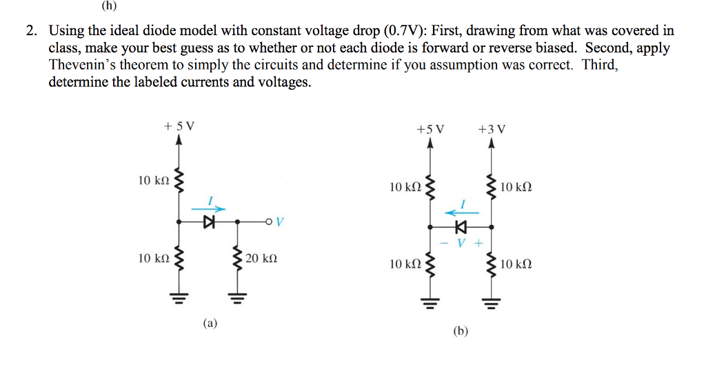
Solved: 2. Using The Ideal Diode Model With Constant Volta... | Chegg.com

GATE-EC - Two silicon diodes, with a forward voltage drop of 0.7 V, are  used in the circuit shown in the figure. The range of input voltage Vi for  which the output
GATE-EC - Two silicon diodes, with a forward voltage drop of 0.7 V, are used in the circuit shown in the figure. The range of input voltage Vi for which the output

Ge and Si diodes start conducting at 0.3 V and 0.7 V respectively. In the  following figure if Ge diode - Brainly.in
Ge and Si diodes start conducting at 0.3 V and 0.7 V respectively. In the following figure if Ge diode - Brainly.in

EE303 - Problem ... O (across the diode) of 0.7 V. (a) Use the diode  small-signal model to show that - [PDF Document]
EE303 - Problem ... O (across the diode) of 0.7 V. (a) Use the diode small-signal model to show that - [PDF Document]

Ge` and `Si` diodes conduct at `0.3 V` and `0.7 V` respectively. In the  following figure if `Ge` - YouTube
Ge` and `Si` diodes conduct at `0.3 V` and `0.7 V` respectively. In the following figure if `Ge` - YouTube